
Propeller operating point and blade twist: input, apparent speed, off-design
The operating point of a propeller is the pair formed by the fluid speed and the rotation speed. The two speeds combine into an apparent speed and an apparent angle on every blade profile, and these set the blade twist (the pitch angle of each section) that suits the propeller. In Heliciel, you enter them in the 1.3: Operating point tab, and the software then computes the geometry and the performance that go with them.
On this page:
- Diagram: propeller operating point configurations
- 1: Entering the operating point in Heliciel
- 2: Apparent speed and apparent angle along the blade
- 3: Tangential speed and blade sections
- 4: From the operating point to the blade twist
- 5: When the operating point changes: off-design mode
Operating point configurations at a glance
A boat propeller can turn one way or the other, and the boat can move ahead, stay moored or move astern. The diagram gathers the configurations Heliciel can compute, with, for each one, the route to follow in the software and how much confidence to place in the result. V is the boat speed, positive ahead; n is the rotation speed, positive in the ahead direction. The blue arrow shows the water arriving at the propeller, without the flow the propeller creates itself. Each one is detailed in §5.
The first four configurations stay within the range where the blade element momentum method is reliable. The next three make the profiles work in deep stall or from the trailing edge: Heliciel computes them and says so, but its figures are trends. The last case, boat moving astern with the shaft turning ahead, would require combining a negative rotation speed with the 180° pitch change: Heliciel does not compute it.
1: Entering the operating point in Heliciel
Here you enter the fluid velocity upstream of the blade, which is the speed of the aircraft, the boat or the wind, and the rotational speed of the propeller if you know it. If you do not, you can let Heliciel find it: that is the job of the optimisation tools described on the page about the optimal rotation speed and number of blades.
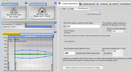
The operating point entry tab: the upstream fluid speed (here in m/s, with its conversion to km/h and knots), the volume flow rate for a ducted propeller, and the rotation speed in revolutions per minute.
The Restore operation points to the last point of design button puts the operating point back to the one the blade was last designed for. It is handy after some off-design trials.
2: Apparent speed and apparent angle along the blade
The fluid speed and the rotation speed each have their own direction: the fluid arrives along the axis, and the blade turns around that axis. They therefore add up to an apparent speed and an apparent angle, which is what the profile "sees" coming. They change with the place on the blade you look at.
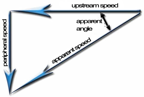
The velocity triangle: the upstream fluid speed and the tangential speed make up the two sides, the resultant is the apparent speed, and the apparent angle is the one it makes with the fluid direction.
This angle thus varies with the rotation speed as well as with the fluid speed. This pair of speeds is the operating point of our propeller.
3: Tangential speed and blade sections
The tangential speed, in m/s, of a point on the blade is the perimeter of the circle it describes multiplied by the number of revolutions per second: v = 2 π r n, with r the radius in metres and n the rotation speed in revolutions per second. If you cut the blade into slices, you find that, for the same rotation speed, a slice at the blade tip moves much faster than a slice close to the axis.
A hypothetical example, to fix ideas: at 10 revolutions per second (600 rpm), a profile 0.10 m from the axis moves at about 6.3 m/s, and a profile 0.50 m from the axis at about 31.4 m/s. If the fluid arrives at 5 m/s, the apparent angle, measured as in the previous figure, is then about 52° near the axis and 81° at the blade tip.
Blade sections are usually airfoils. The part of the blade between two profiles is a blade element: on each of these elements, the BEM (Blade Element Momentum) method draws up its force balance.
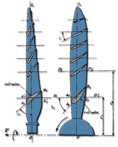
A blade seen from the front and from the side: the inclination of the profiles changes from one radius to the next, which is the twist.
4: From the operating point to the blade twist
Since the speed of a profile at the blade tip differs from that of a profile close to the axis, the relative flow varies in angle and in speed with the distance from the propeller axis. For the angle of attack of every profile to stay at its optimum, the pitch angle (the angle between the plane of rotation and the chord of the profile) must therefore vary with the direction of the relative flow. This is the twist of the blade.
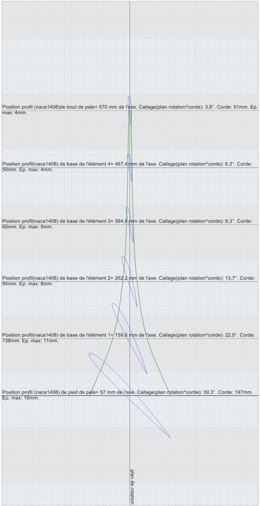
The blade twist drawing computed by Heliciel: from 39.3° at the blade root to 3.8° at the tip, according to the values written on the drawing.
The operating point therefore also determines the twist. A blade is twisted so that its angles are optimal at one precise operating point.
5: When the operating point changes: off-design mode
If the rotation speed or the fluid speed varies, the twist of the blade no longer suits it. The propeller then works outside its design point: this is the off-design mode. Its profiles leave the angle of attack they were set for, and their lift-to-drag ratio drops. Heliciel handles both situations:
- rebuild the optimum twist for the new operating point

- calculate the off-design performance of the existing blade

To see what really happens on the blade, let us follow the same profile through several operating modes. The example is a 350 mm, 3-blade boat propeller designed for 863 rpm and 3.86 m/s (7.5 knots) in sea water. The profile shown is that of element 6, 122 mm from the axis, about 0.7 times the radius: the usual reference radius for the pitch of a propeller.
5.1: The angles Heliciel draws on each profile
For each blade element, Heliciel draws the profile in its plane of rotation, with three directions. On these images, all angles are measured from the plane of rotation (the black vertical line):
- the apparent angle (yellow line): the direction of the fluid as seen by the profile, combining only the advance speed and the tangential speed. Its tangent is advance speed / tangential speed;
- the real angle (blue line): the same direction once the velocities induced by the propeller itself are added (axial acceleration of the fluid and swirl of the wake). This is the flow the profile actually meets;
- the pitch angle (grey line): the inclination of the profile chord, set when the blade is made.
The effective angle of attack of the profile is the difference between the pitch angle and the real angle. It decides the lift and drag of the profile, and therefore everything else.
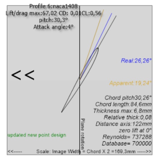
At the design point, the apparent angle is 19.24° and the real angle 26.26°: the induced velocities turn the flow by 7°. Heliciel set the profile at 30.26°, so as to leave it exactly 4° of angle of attack, the one of its best lift-to-drag ratio (67). That is what a blade twisted for one operating point means.
5.2: The boat goes slower: the angle of attack increases
Let us keep 863 rpm, but with a boat at only 2 m/s (a loaded boat, or one accelerating). The advance speed drops, the tangential speed does not change: the flow reaches the profile at a flatter angle.
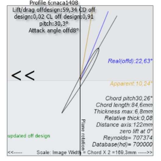
The apparent angle falls to 10.24°. The induced velocities grow with the blade loading and make up part of the difference: the real angle only falls to 22.63°. The angle of attack still goes from 4° to 7.6°. The profile lifts much more (CL 0.91 instead of 0.56) and the propeller pushes harder (1,332 N instead of 933 N), but the lift-to-drag ratio drops (59 instead of 67) and the propulsive efficiency falls to 0.39.
5.3: The boat goes faster: the angle of attack decreases
Conversely, at 5.5 m/s and still 863 rpm, the flow straightens towards the axis.
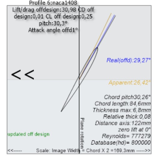
The real angle (29.27°) almost reaches the pitch angle: only 1° of angle of attack is left. The profile is unloaded (CL 0.25) and its lift-to-drag ratio collapses to 31. The thrust falls to 478 N: the propeller turns too slowly for this speed. Its propulsive efficiency, on the other hand, rises to 0.79 (0.65 at the design point): a lightly loaded propeller loses little energy in its wake, but it no longer delivers the expected thrust.
5.4: Bollard pull: the profile stalls
Boat moored, propeller at 863 rpm: the advance speed is zero. This is the case of a tug pulling on its bollard, or of a boat starting off.
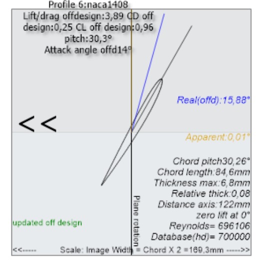
The apparent angle is zero: with no advance speed, the fluid arrives in the plane of rotation. Only the flow the propeller draws in itself gives a real angle of 15.88°. The angle of attack rises to 14°, beyond the stall of the profile: the drag shoots up (CD 0.25) and the lift-to-drag ratio is only 3.9. The propeller pulls 1,353 N, but it absorbs 8.1 kW to do so, against 5.5 kW at the design point. See also the page on propeller performance at zero speed.
5.5: Controllable pitch gives the profile its angle of attack back
Let us go back to the faster boat of §5.3, whose profiles were working at only 1° of angle of attack. A controllable-pitch propeller can turn all its blades by the same angle. With 5° more pitch, element 6 goes from 30.26° to 35.26°:
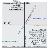
The real angle increases too (31.91° instead of 29.27°), because the more heavily loaded blade induces more: the 5° added only give back 2.3° of angle of attack. The profile gets back to 3.3° of angle of attack and a lift-to-drag ratio of 62. The thrust rises to 885 N, almost that of the design point, with a propulsive efficiency of 0.74. The pitch variator of the 3D view lets you run this test on any propeller.
5.6: Going astern: the profile attacked by its trailing edge
Now let us reverse the direction of rotation of the shaft while the boat is still moving ahead at 3.86 m/s: this is the crash-stop manoeuvre of a fixed-pitch propeller. The profile moves backwards, and the fluid reaches it at the trailing edge, at an angle of attack of about 160°. The profile is no longer a lifting profile: it behaves like an inclined flat plate, in deep stall. Over most of the blade, the jet the propeller throws forward overcomes the boat speed, and the fluid crosses the disc the wrong way.
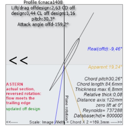
On the image, the fluid directions (yellow and blue) now point downwards, on the trailing edge side. The angle of attack seen by the profile is −159.2°. The profile keeps a CL of 1.16, but its drag is huge (CD 0.44): its lift-to-drag ratio is only 2.6.
Heliciel computes this regime when a negative rotation speed is entered. Here it finds 1,503 N of braking force for 10.2 kW absorbed. These values are a trend rather than a precise operating point, because the flat-plate polars and the momentum theory are then outside their range. Heliciel says so at every calculation.
Another case: the boat moves astern, shaft reversed. Once the boat has stopped and started moving backwards, the speed and the rotation are both reversed. This case is computed differently: turning the propeller half a turn about a radius reverses both the direction of the axis and the direction of rotation. Reversing speed and rotation is therefore exactly the same as adding 180° to the pitch angle of every section, at normal speed and rotation. In Heliciel, you get it with the pitch variator of the 3D view set to +180° or −180°, or in reverse engineering mode by adding 180° to the measured pitch angles.
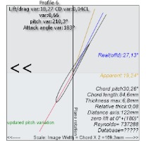
The pitch angle goes from 30.26° to 210.26°: the chord keeps the same inclination, but the trailing edge is now in front. The fluid reaches it only 3° from the chord line (real angle 27.13°). Heliciel finds a balance over the whole blade: 1,046 N of thrust astern for 7.1 kW, with a propulsive efficiency of 0.57, against 933 N and 0.65 going ahead.
For a profile attacked by its trailing edge, 3° from the chord line, Heliciel finds CL 0.66 with a lift-to-drag ratio of 18. This value comes from the polar built around 180° (flat-plate model, with no camber or thickness), not from a calculation of the actual profile running backwards. A cambered profile working backwards has its camber the wrong way round and meets the fluid with a sharp edge: it can be expected to lift less and drag more. The thrust and efficiency astern are therefore probably overestimated. The mechanism is right; the figure remains a trend.
5.7: Summary
| Mode (element 6, r = 122 mm) | Advance speed | Apparent angle | Real angle | Pitch angle | Effective angle of attack | CL | Lift/drag | Propeller thrust |
|---|---|---|---|---|---|---|---|---|
| Design point | 3.86 m/s | 19.24° | 26.26° | 30.26° | 4.0° | 0.56 | 67 | 933 N |
| Slower boat | 2 m/s | 10.24° | 22.63° | 30.26° | 7.6° | 0.91 | 59 | 1,332 N |
| Faster boat | 5.5 m/s | 26.42° | 29.27° | 30.26° | 1.0° | 0.25 | 31 | 478 N |
| Bollard pull | 0 | 0° | 15.88° | 30.26° | 14.4° | 0.96 | 3.9 | 1,353 N |
| Faster, pitch +5° | 5.5 m/s | 26.42° | 31.91° | 35.26° | 3.3° | 0.50 | 62 | 885 N |
| Crash stop | 3.86 m/s | 19.24° | −9.46° | 30.26° | −159.2° (at the trailing edge) | 1.16 | 2.6 | 1,503 N braking |
| Boat moving astern (pitch +180°) | 3.86 m/s astern | 19.24° | 27.13° | 210.26° | −176.9° (at the trailing edge) | 0.66 | 18 | 1,046 N astern |
All values are computed by Heliciel at 863 rpm, the blade geometry remaining that of the design point. The effective angle of attack is the difference pitch angle − real angle; the images round it to the degree.
The diagram at the top of the page places all these cases, as well as the one Heliciel does not compute.
The Images 2d profiles menu opens the drawings of all blade elements, one tab per element. In the 3D view, clicking a blade element also shows the profiles at its base and tip, with their angles. The drawings are updated at every calculation: design point, off-design, pitch variation or going astern.
To go further, we can compare several operating points in one go with the multiple operating point analysis, or see how to change the pitch angle and the pitch of the blade to suit a given point.
 Global site map
 Mecaflux
 Tutorials Mecaflux Pro3D
 Tutorials Heliciel
 Tutorials Heliciel PRO CFD
 Mecaflux Store
 Compare software functions
 Quotes, Orders, Payment Methods
 project technical studies